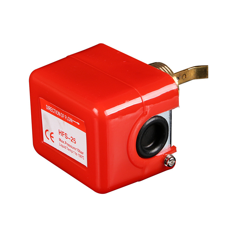
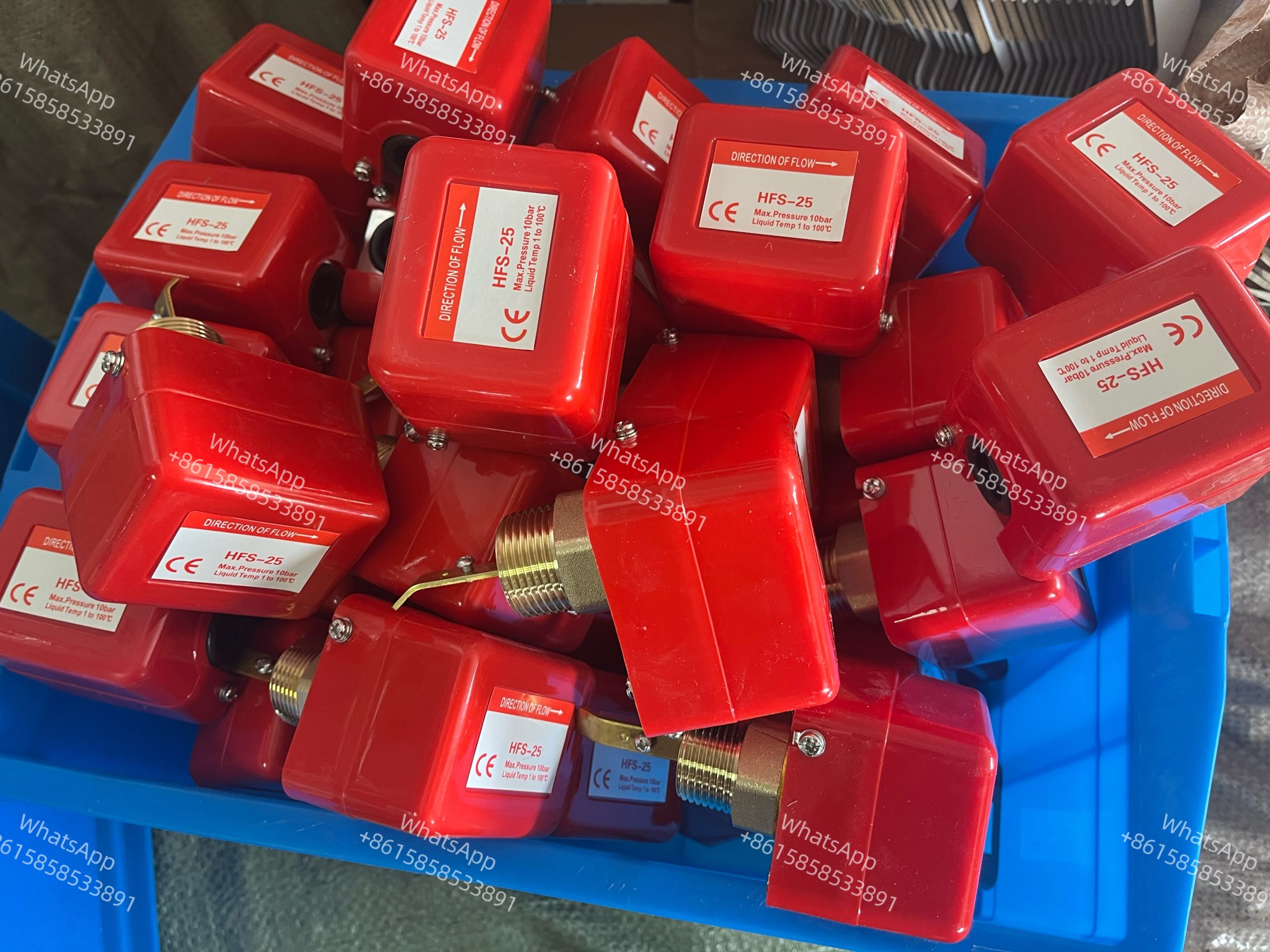
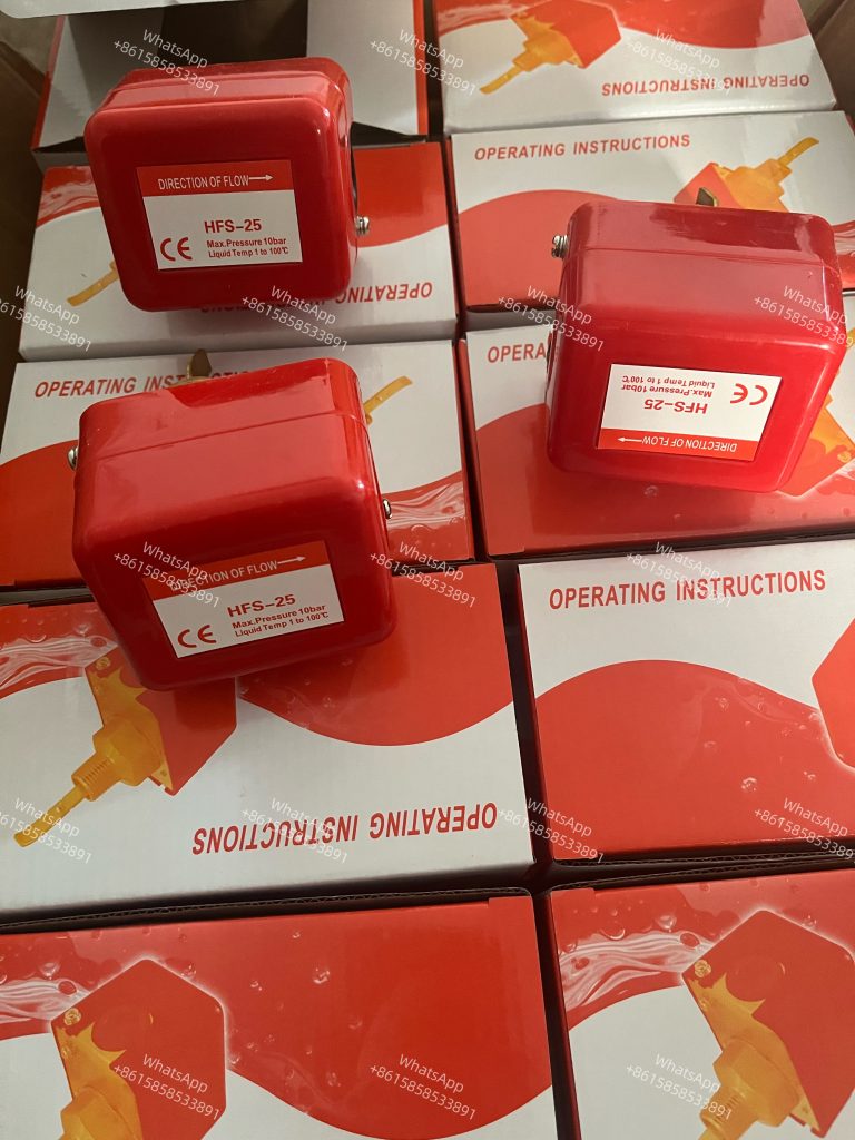
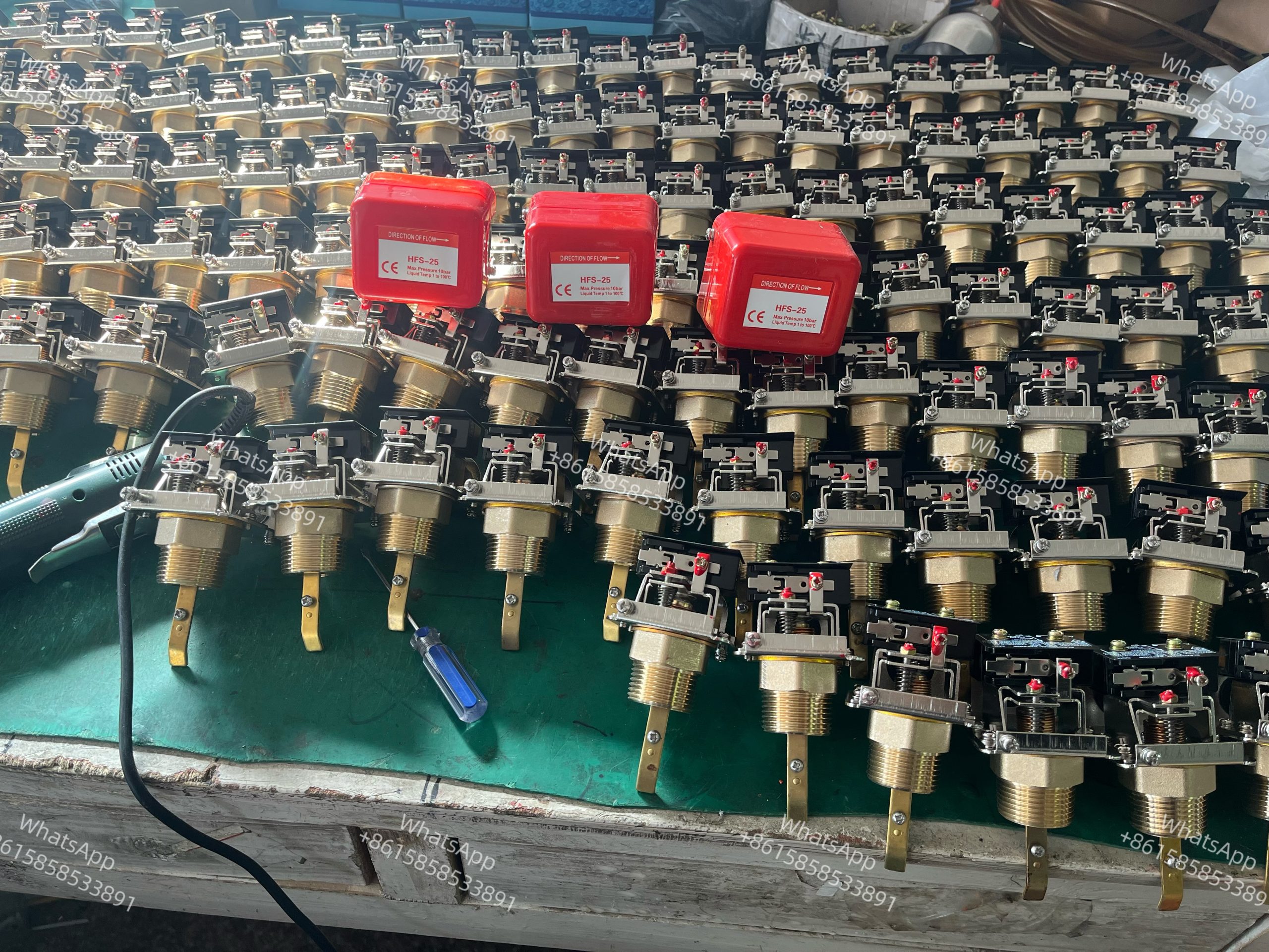
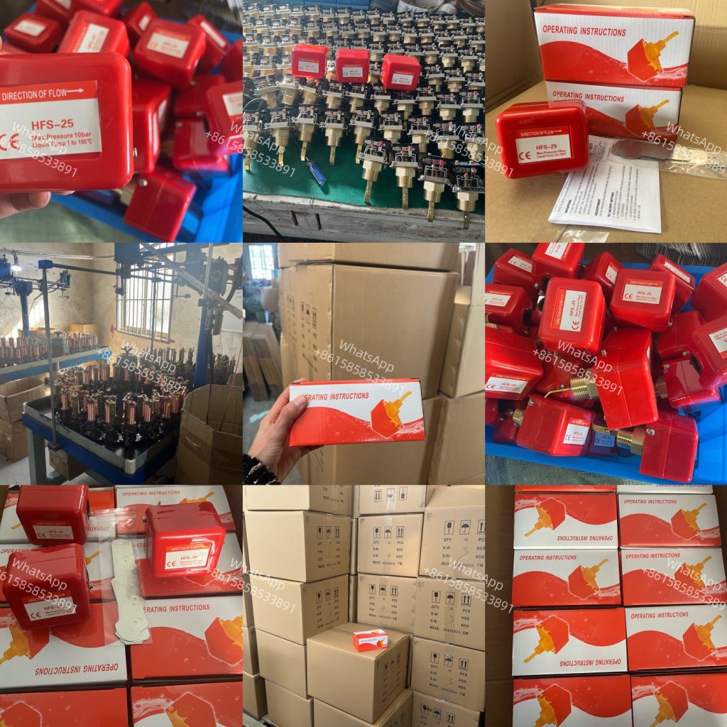
Flow Switch, Water Flow Switc Hfs-15 ,Hfs-20,Hfs-25
Paddle Flow switch,Công tắc dòng chảy HFS 20 HFS 25
1, With extremely small pressure loss
2, Good repeatability
3,With high anti-stain ability
4,Accurate switch setup through knob
5,The mechanical part isolate with electric part totally .
6,It will provide 5 kinds of baffle. When small flow rate in big diameter pipe or the pipe is not fulfill it , user can change it according to the field situation . Also , it make one type flow switch to suit for different size pipe .
Hfs Series G1/2 G3/4 G1 Brass Fire-Resistant Liquid Control Sensor Pneumatic Valve Flow Switch
Product Description
HFS Paddle Flow Switch is an automatic control unit which switches on or off in response to the flow or non-flow of a liquid media. The switch typically operates through the use of a paddle which gets displaced due to the force of fluid moving past it.
Flow switches enable the reliable and process-safe monitoring of fluid. When the flow is above or below the set value, built-in SPDT micro switch activates downstream regulator or control, such as a pump, an alarm, a water chiller or heat exchanger. Damage and production losses through degradation of pumps, tools and spindles can thus be avoided.
Features
|
Operating Pressure: 10kgf/cm² (1MPa) Withstand Pressure: 17.5Kgf/cm² (1.75MPa) Insulation Resistance: Over 100Ω, DC500VM Withstand Voltage: AC1500V/1minute Micro Switch Lifetime: 500K Cycles Bellows material: tin-phosphor bronze (stainless steel available) Bellows Lifetime: 300K Cycles Connection threads: (BS)PT (NPT and (BS)PP available upon request) Threads material: brass (stainless steel available) Protection class: IP44 Temperature of media: -10~100°C (not lower than its freezing point) |
Technical Drawing

Electrical Parameter
| Rated Amps(A)\Rated Voltage(V) | Horsepower | 125 VAC | 250 VAC | |
| Non-inductive Amps | 1 | 15 | 15 | |
| Inductive Amps | Rated Amps | 0.75 | 3.5 | 2.5 |
| Locked Rotor Amps | 0.45 | 21 | 15 | |
Flow Adjustment Table
| Model | Pipe Size (Inch) | Flow. Adjustment Range (L/min) | |||
| Minimum adjustment | Maximum adjustment | ||||
| Decrease | Increase | Decrease | Increase | ||
| HFS-15-SS
HFS-20-SS HFS-25-SS |
1 | 18 | 21 | 45 | 50 |
| 1-1/2 | 30 | 35 | 100 | 105 | |
| 2 | 50 | 58 | 150 | 155 | |
| 2- 1/2 | 75 | 86 | 187 | 200 | |
| 3 | 100 | 115 | 225 | 260 | |
| 4 | 110 | 154 | 317 | 337 | |
| 5 | 170 | 236 | 462 | 490 | |
| 6 | 225 | 308 | 562 | 599 | |
Mounting
Flow switch be mountedin a horizontal pipe line or vertical pipeline .
Mount the instrument in a section of pipe where there is a straight run of atleast 5pipe diameter on each side of the flow swhtch
Adjustment
Note :sealed adjustments are not field addjustable .
Adjust Setting
1,Remove switch cover
2,For higher flow rater-turn range adjusting screw clockwise
3,For lower flow rater-turn range adjusting screw counter clockwise.
4,Be sure flow swtich cover is replaced before leaving job.
สินค้าที่เกี่ยวข้อง
-
Pneumatic Control Valve
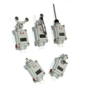
Explosion Proof Limit Switch BLX51-B/BLX51-H/BLX51-N
-
Pneumatic Control Valve
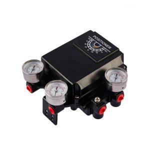
YT1200 Series Pneumatic Valve Positioner
-
Pneumatic Control Valve
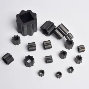
Double Square Adapter
-
Pneumatic Control Valve
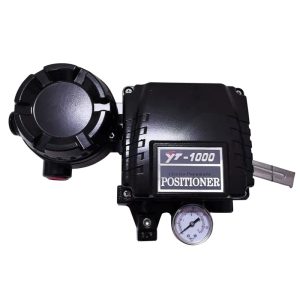
YT1000 Linear ElectroPenumatic Positioner

